Schedule for Bar Bending [BBS] Steel Estimate for Building Construction
Bar Bending Schedule [BBS] Overview:
“BBS” the letter BBS plays a significant role in any high-rise building construction. Bar Bending Schedule is referred to as BBS. So, what purpose does BBS serve? Why do we use a BBS? Describe BBS.
In this article, we mainly concentrate on how to start, where to start, and what the fundamentals are. In addition to this, you can lea
BBS - Bar Bending Schedule
Be prepared to read this article for at least 10 minutes because it's lengthy. Let's get going.
To begin with, rebar of any kind used as reinforcement in RCC is referred to as "Bar." The bar could be made of TMT, HYSD, or mild steel.
The term "Calculation of the total Steel Required for the Construction of a Building" refers to the Bar Bending Schedule. Steel is used to make reinforced concrete and to meet tension requirements. But how much steel is needed to build a structure with 15 floors? How much steel do I need to purchase? In BBS, all of these inquiries have answers.
In the bar bending schedule, the bars are arranged for each structural component (beams, columns, slabs, footings, etc.), and a detailed list is created that details the bar's location (in footings, slabs, beams, or columns), bar size (the length of the bar used), quantity (the number of bars used), cutting length, type of bend, and shape in the reinforcement drawings.
How BBS Has Changed Since 1950:-
From 1950 to 2019, our world has undergone numerous changes and improvements. Three-story buildings were considered high rises in 1950; today, we are building a structure with more than 200 floors. The construction sector is expanding significantly. The massive increase in global population necessitates more facilities, more construction, and a need for more space.
B.N. Datta, the father of estimation, has made some recommendations regarding the use of steel in various building components. But if we use more bars in a single structural member, he didn't mention any values.
| Bar Bending Member | Percentage |
|---|
| Slab | 1% of total volume of concrete |
| Beam | 2% of of total volume of concrete |
| Column | 2.5% of total volume of concrete |
| Footings | 0.8% of total volume of concrete |
Based on a load analysis, we are now using more than 12 bars in columns, up from just four at the time. As a result, a column's percentage of steel is increased, showing that the values previously mentioned are out of date. (They're out of date but "not wrong") It was written by him in 1950. The year 2019 is now. According to the potential for construction at the time, he made recommendations. We are currently building more than 200 floors in the limited space.
Schedule for Bar Bending [BBS]:
It's imperative to understand the fundamentals of the bar bending schedule before dealing with the BBS. A starting point for learning bar bending schedule from scratch is the table below.
| S.No. | Particulars | Result |
|---|
| 1. | Standard Length of the Steel Bar
(Bars are sold at standard Length)
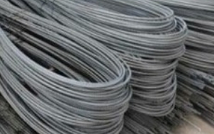 | 12m or 40' |
| 2. | Weight of Bar
for length = 1m | D2/162
(were D = Dia of Bar)
|
| Ex: | If length of bar is 12m with 10mm Dia then ,
Weight of bar = D2/162
Therefore for length 1m = 1m x D2/162
= 1 x 10²/162 = 0.61 Kgs
For length 12m = 12 x 102/162
= 7.40Kgs | 7.40Kgs |
| 3. | Density of Steel | 7850Kg/m3 |
I go over several Bar Bending Schedule concepts that are very helpful when using BBS in the sections below. Any structural member's BBS design calculation uses all of these concepts. Therefore, become familiar with the ideas below. To make things clear, the concepts are first explained, and then this post is concluded with an example of a member's BBS calculation.
1. Stirrups' hook length or cutting length:
For ties in columns and stirrups in beams, the hook length is frequently specified. Typically, stirrups or ties with hooks are added to the two ends of the rebar.
Hook Length = 9d (d is the bar's diameter)
Below image makes you clear why the Hook length = 9d
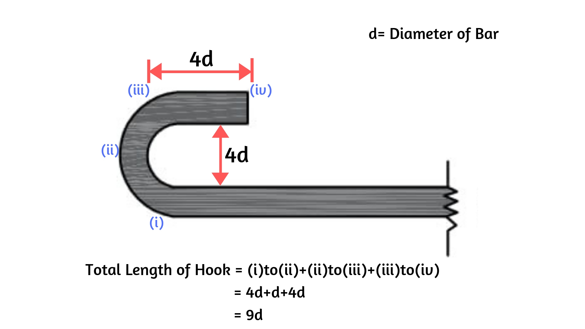
From above fig, length of hook = [(Curved Portion) + 4d] = [(4d+d)+4d] = 9d
Hook Length = 9d [d is the Bar's Diameter]
Example of a calculation taking into account stirrups with end hooks:
Look at the illustration below for a clear understanding of how to calculate the total length of a stirrup with two hooks at each end.
Stirrup or tie total cutting length equals total bar length plus two times the length of the hooks (two hooks).
L+2(9d) = Total Cutting Length
Therefore, Total Cutting length is L plus 18d (d is a bar's diameter).
I believe you are now clear on how to calculate the hook length.
For cranked bars (bars that have been bent up) and bends at corners, the bend length calculation is different.
The majority of the time, the bars are cranked in slabs and are bent at the corners in stirrups or ties.
(i) Cranked bar bend length calculation:
As the supports in a slab are under the most shear stress. We typically crank the bars at the ends of slab supports to resist these stresses. The bent up bar in Slab is shown in the figure below. The steps listed below should be followed to calculate the bend length.
As seen in the previous figure, when the bar is bent at an angle of 0 degrees, an extra length (la) is added.
In this case, la = l1 - l2-(i)
Sin = D/l1 while Tan = D/l2
As a result, l1 = D/Sin and l2 = D/tan.
Consequently, from (i)la = D/tan - D/Sin
Giving various values, such as 300, 450, and 600, yields various additional length la values, as shown below.
| θ0 | D/Sinθ | D/tanθ | la =D/Sinθ – D/tanθ |
| 300 | D/0.500 | D/0.573 | 0.27D |
| 450 | D/0.707 | D/1.000 | 0.42D |
| 600 | D/0.866 | D/1.732 | 0.58D |
| 900 | D/1 | 0 | 1D |
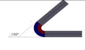
| 1350 | D/0.707 | D/-1 | 2.42D |
If the bars are turned at a specific angle, the extra length is added to the overall length of the bar.
An example calculation taking into account a cranked bar in a slab is as follows:
An additional bar of length (L/4) is provided below the crank bar as shown in the figure below in order to keep it in place.
As a result, 1.5L+0.84D = L+0.42D+0.42D+(L/4)+(L/4) = the total length of the bar.
Never forget: D = Depth of Slab, Top Cover, and Bottom Cover.
(ii) Calculating the Bend Length when Bending Bars at Corners:
The crucial criteria used to determine the bend length at corners
45° Bend length equals 1d
90° Bend length = 2d
135 degrees Bend length 3d
equals 'd' here denotes the bar's diameter.
Example of a calculation taking into account a stirrup with corner bends:
Three bends in the above figure are bent at an angle of 900 degrees, while two other bends are bent at a 1350 degree angle.
Bend length overall = 3 x 900 Bend length plus 2 times 1350 Bend length equals 3 x 2d plus 2 x 3d, or 12d, 12 x 8, or 96mm.
Find out more about determining the stirrup cutting length in columns and beams for various shapes.
The total length of the bar calculation for various bar shape types is shown in the table below.
(If you want a clear view of the table below on a mobile device, scroll horizontally.)
| Bar Shapes | Total Length of Hooks | Total Bend Length | Total Length of Bar |
|---|
Straight Bar
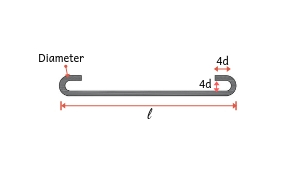 | Two Hooks
= 9d + 9d
= 18d | No bend | l + 18D |
Bent Up at one End only
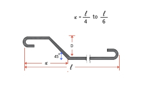 | Two Hooks
= 9d + 9d
= 18d | One bend
bent at an
angle 45
= 0.42D | l + 18D + 0.42D |
Double Bent up Bar
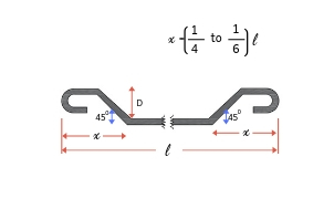 | Two Hooks
= 9d + 9d
= 18d | Two bends
bent at an
angle 450 | l + 18D + 0.42D + 0.42D
=l+18D+0.84D |
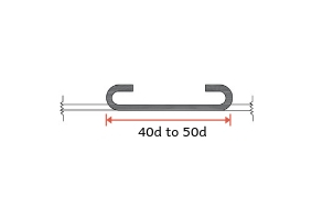
Overlap of bars
 | Two Hooks
= 9d + 9d
= 18d | No bends | Overlap Length
=(40d to 45d)+18d |
3. Reinforcement Overlap Length / Lap Length:
Rebar's standard length is 12 metres. Let's say the column is 20 metres tall. Two bars with lengths of 12 metres and 8 metres are overlapped (joined) to fulfil this requirement.
Have you noticed the image below on your building's top floor? On the bottom floor, we typically project a certain length of bar, say 50D. It serves the purpose of continuing construction. (Building a fresh floor)
Also see: Bar Bending Schedule Development Length
How to Create a Schedule for Bar Bending:
To make things clear, I've created a BBS for the RCC Column structural member that is below.
BBS of Column |
|---|
| Structural Member | Column
(3mx0.3mx0.3m) |
| Bar Marking | 1. Main Bars
2. Stirrups (Longitudinal bars) |
| Dia of Bar | 1. Main Bars = 16mm ;
2. Stirrups
(Longitudinal bars) = 8mm |
| No. of Bars used | 1. Main bars = 4
2. Stirrups = 30 |
| Cutting length | 1. Main bars = 3.16m
2. Stirrups = 2.64m |
| Total Length of bar | 1. Main bars = 18.4m
2. Stirrups = 43.2m |
| Weight of Steel bar | 1. Main bars = 29Kgs
2. Stirrups =17Kgs |
Calculations for the table above:
Calculating the number of bars:
4 main bars
Use 0.1 m as the distance between the bars when calculating the number of longitudinal bars.
Length of column / Spacing = 3/0.1 = 30 bars for the number of longitudinal bars.
30 longitudinal bars
Calculating the cutting length:
Main bars equal 4.6m, 3m, 50d, and 50d, respectively.
Stirrups:
Hook length is 9d plus 9d plus 18d plus 180.08=1.44m.
Bend length equals 3 x 900 Bend length plus 2 times 1350 Bend length is calculated as 3 x 2d + 2 x 3d = 12d = 12 x 8 = 0.096m.
= l + hook length + bend length, or 0.3 + 0.3 + 0.3 + 0.144 + 0.096 = 1.44 m.
In light of this, Main Bars = 4.6m and Longitudinal Bars = 1.44m
Total Length of Bars: The total length of the main bars is equal to the number of main bars times the length of one bar, or 4 times 4.6 metres.
Total length of longitudinal bars equals the number of longitudinal bars times the length of one bar, or 30 x 1.44, or 43.2 m.
Steel bar weight: 1 m x D2/162 = 1 m steel bar weight
18.4 x 162/162 = 29 kgs total weight for the main bars
Longitudinal bars weigh a total of 43.2 x 82/162 = 17 kg.
46 kg is the total amount of steel bar needed to complete the above column's BBS.
Important guidelines for creating a bar bending schedule include:
- For each structural unit, the bars used in a building should be listed collectively, and separately, for each floor.
- The order of the bars is numerical.
- Each bar in the bundle of bars is specifically labelled with reference information (bar length, bar size, bar shape) to help you identify it.
- The type of bar and the bar's shape must both adhere to B8666.
- A specific group or set of bars with specific length, size, shape and type used at work must be specifically referred to by the bar mark reference on the label that is attached to a bundle of bars.
- The calculations for cutting length and bending length are done separately and are not listed in the comprehensive list. In the same way that I've listed the specifics of bar bending in a table and performed separate calculations.
Schedule for Bar Bending:
- BBS aids in estimating the overall amount of steel needed to construct a building or other structure. The price of steel should be included in the quote for the tender.
- Finding the cutting length and bending length in reinforcement detailing enhances construction quality, reduces steel waste, and results in an affordable construction.
- Cutting and bending can be done in the factory and transported to the site with the aid of reinforcement drawings. This speeds up construction and lowers the overall cost of the project.
- Before pouring the concrete, it is simple for site engineers to check the cutting and bending lengths of the reinforcement.
Calculator for Bar Bending Schedule:
Determine the required amount of steel.
Schedule For Bar Bending | How To Create A Schedule For Bar Bending
Schedule for Bar Bending (BBS)
The length of each bent and straight portion, the angle of bending, the total length of each bar, and the quantity of each type of bar are all included in the bar bending schedule, which is a table of data.
For the site engineer who is working on-site and creating estimates and bills of materials, this information is very helpful.
Continue reading: What Is Steel Unit Weight? | Steel Unit Weight Formula
How Are Bends Subtracted From Schedules for Bar Bending?
When determining the Bar Bending Schedule, the Bend Deductions are crucial. Basically, we will be considering how much of the bar length should be cut while bending it.
Many of us believe that we need more length than is necessary in order for the bar to reach its ideal length after being bent. However, this is untrue.
The 12 m-long reinforcement bars that are available on the market.
Due to the steel's elasticity and ability to deform, the length of the bar increases as it is bent.
As a result, depending on the angles, the deductions will vary for the various bents.
These are the deductions:
The bar's diameter is d.
1. The deduction for a 45-degree bend is d.
For instance, the diameter of a bar with a 12 m (assumed) length is 25 mm. Therefore, d subtracts it for one bend.
i.e.
Cutting Length is equal to 12 d/12 0.025 m, or 11.975 m.
Therefore, after bending, only a bar of length 11.975 metres is required to produce a 12 metre bar.
The length of the bent bar will be 12 m if we bend a 12 m bar.
= 12 + d = 12 + 0.025 = 12.025 m, which is more than is needed.
2. The deduction is the same for a 90-degree bend: 2d.
For instance, the diameter of a bar with a 12 m (assumed) length is 25 mm. As it is a 90-degree bend, the first bend is therefore reduced by 2d.
i.e.
Cutting Length is equal to 12- 2d/12-2*0.025, or 11.95 metres.
3. The deduction is the same for a 135-degree bend: 3d.
For instance, the diameter of a bar with a 12 m (assumed) length is 25 mm. As a result, one bend is subtracted by three because it is a 135 degree bend.
i.e.
Cutting Length is calculated as 12- 3d/12-3*0.025=11.925 m.
4. The deduction is the same for a 180-degree bend: 4d.
For instance, the diameter of a bar with a 12 m (assumed) length is 25 mm. Since there is only one bend and it is a 180-degree bend, 4d is subtracted.
i.e.
Cutting Length = 12 3d x 12 4 x 0.025 m.
To obtain the cutting length, there should be n deductions from the original length for every n bends.
For instance,
12 metres in length, 25 millimetres in diameter, 90 degrees bent, and two bents.
Cutting Length is therefore equal to 12- 2*(2d)= 12- 2(2*0.025)= 11.9 m.
Regardless of the angle, we will typically only deduct 2d for each bend on a construction site (i.e., regardless of the angle being 45 degrees, 90 degrees, 135 degrees, or 180 degrees, we will only deduct 2d for each bent).
For more information, consult the "IS:2502 Code of Practise for Bending and Fixing of Bars".
Read more: Excel Calculation of Steel Quantity
How to Create a Schedule for Bar Bending
Let's use the reinforcement of an RCC slab as an example to calculate and prepare a schedule for bar bending.

Section of RCC Slab Reinforcement
Details of RCC Slab Reinforcement
- 12 mm diameter at 150 c/c for the main bent up bars
- 8 mm diameter distribution steel bars at 180 c/c
- 50 mm for the side cover
- 20 mm for the top and bottom covers
- Every hook is 90 degrees.
- Bent Up Equals 45 Degrees

Details of RCC Slab Reinforcement
SR.
No. | Descriptions | No | Length | Breadth | Height | Quantity |
| 1 | 12 mm dia main Steel bars
@ 150 mm c/c Alternate
bent up.
| | | | | |
| L = Span Length + Wall Width(Right) + Wall Width (Left) + 2 x 9D (Hooks) – 2xCover
L = 3 + 0.23 + 0.23 +
(2 x 9 x 0.012) – (2 x 0.05) | | | | | |
| L = 3.58 m (Straight length without bent) | | | | | |
| | | | | | |
| Span = 4 + 0.23 + 0.23 – (2 x 0.05)
= 4.36 m | | | | | |
| No. of Bars = (4.36/0.15) + 1 = 30 nos. | | | | | |
| | | | | | |
| Extra Length of Bent up: | | | | | |
|  X – Value X – Value | | | | | |
| Extra Length = 0.45 X | | | | | |
| X = 0.12(Slab Thickness) – 2 x 0.02 (Top & Bottom Cover) – 0.012/2(Harf dia top) – 0.012/2( Half dia bottom) | | | | | |
| L = 3.58 + 0.45X
L = 3.58 + 0.45 x 0.068
L = 3.61 m | 30 | 3.61 | @ | 0.89 | 96.38kg |
| (Note: In case of bent up bars are provided on both sides, we have to add 0.45 X twice in length) | | | | | |
| | | | | | |
| 8 mm dia. Distribution steel @ 180 mm c/c | | | | | |
| Bars at Bottom: | | | | | |
| Hook Length = 9d
= 9 x 0.008
= 0.072 < 0.075
( Mini. Hook length = 0.075) | | | | | |
| L = 4 + 0.23 + 0.23 + 2 x 0.075(Both side hook(9d) | | | | | |
| L = 4.51 m | | | | | |
| Width of Slab = 3 + 0.23 + 0.23 – 2 x 0.05 (Both Side Cover)
= 3.36 m | | | | | |
| No. of Bars = (3.36 / 0.18) + 1
= 20 nos. | | | | | |
| | | | | | |
| Bars at Top: | | | | | |
| Width of Slab at one end for bent up at Top | | | | | |
| L= 0.23 + 0.45 – 0.068 – 0.05(cover) | | | | | |
| L = 0.562 m | | | | | |
| | | | | | |
| Nos. of Bars at one End:
= (0.562/0.18) + 1
= 5 nos. | | | | | |
| Nos. of bars at both side
= 2 x 5 = 10 | | | | | |
| Total Bars = 20 + 10 =30 | 30 | 4.51 | @ | 0.40 | 54.12 kg
|

Bar Bending Schedule (BBS) Benefits
1. Reinforcement can be cut and bent at the factory and transported to the site if a schedule for bar bending is available.
Due to a decrease in the number of workers needed to bend bars, this results in quicker execution on site and decreases construction time and cost.
Bar bending also reduces project costs by preventing the loss of steel reinforcement (5 to 10%).
2. Compared to Fe415 using a bar bending schedule can save 10% more steel reinforcement.
3. Because reinforcement is provided in accordance with a bar bending schedule that is created using the guidelines of the relevant detailing standard codes, the quality control at the construction site is improved.
4. It offers a more accurate estimate of the amount of reinforcement steel needed for every single structural member, which can be used to determine the total amount of reinforcement needed for the entire project.
5. It offers better reinforcement stock management. Accurate estimates of the amount of steel needed for the upcoming construction phase are possible, as is procurement.
In cases where reinforcement is in coastal areas, this prevents storage of additional steel reinforcement at the site for an extended period of time.
By providing an accurate estimate, it also avoids a shortage of reinforcement for ongoing projects, allowing for the smooth progress of concrete construction projects.
6. A schedule for bar bending is very helpful when auditing reinforcement and offers checks on theft and pilferage.
7. Before a structural member can be positioned at the required location, reinforcement can be cut, bent, and made into a skeleton using a bar bending schedule.
This activity can be carried out concurrently with other activities like excavation, PCC, etc. As a result, managing all project activities is made simple, which shortens the construction period. It helps in avoiding any damages brought on by construction time overruns.
8. It offers benchmarks for the quantity and quality demands for concrete and reinforcement works.
9. The bar bending schedule offers a much more accurate estimate of the required quantity of steel and, as a result, gives the option to optimise the design in the event of cost overrun.
10. The use of a bar bending schedule makes it simple for site engineers to confirm and approve the bar bending and cutting length during an inspection prior to the placement of concrete and aids in better quality control.
11. It makes it simple and quick for clients and contractors to prepare construction work invoices.
12. There is no option for estimating the quantity of steel reinforcement because it must be calculated according to engineering formulas and standard codes.
13. By using a bar bending schedule, it is possible to automate the cutting and bending of reinforcement, which again lowers project costs, duration, and reliance on skilled labour. Additionally, it increases the accuracy and dependability of bar bending and cutting.
14. The cost of reinforced concrete work per unit decreases and aids in cost optimisation of construction projects when mechanised bar cutting and bending is used.
What Is a Schedule for Bar Bending?
The length of each bent and straight portion, the angle of bending, the total length of each bar, and the quantity of each type of bar are all included in the bar bending schedule, which is a table of data.
bending a bar
A table of data for bar bending includes different steel diameters, the shape of the bending, the lengths of the bent and straight portions, the bending angles, the overall length of each bar, and the quantity of each type of bar.
What is a schedule for bar bending?
A tabular representation of reinforcement bar is known as a bar bending schedule or schedule of bars. For every type of R.C.C work, it is typically represented.
The requirement for various lengths and sizes of bars may be known and can be arranged and bent-up during the time of construction with the aid of a bar bending schedule.
The general description of a bar bending schedule includes the specifics of the bars, the shape of the bending with sketches, the total length and weight of the bars, as well as their numbers.
A schedule for bar bending is typically created when estimating a R.C.C. work or structure.
Benefits of BBS
- Calculating steel reinforcement quantities of various diameters and grades is simple.
- A schedule of bars makes it simple to find ideas for various bar sizes, bends, and lengths.
- The bar bending schedule is very useful when inspecting the reinforcement on a construction site.
- Additionally, it aids in reducing confusion on the construction site.
- It provides the precise amount of steel needed for the job, allowing for the optimisation of reinforcement in the event of cost overruns.
- Site engineers can easily check and confirm the cutting length and bar bending while inspecting the site thanks to the bar bending schedule.
- These bar schedules make it simple to create the construction bills at the conclusion of the entire project.
Additional Reading: Curved Roof: Construction, Benefits, and Drawbacks
Additional Reading: Civil Engineering Value Types
Additionally, see Remote Sensing: Definition, Classification, and Techniques.
How to Create a Schedule for Bar Bending
In general, two items can be used to calculate reinforced cement concrete works:
1. Centering and shuttering of concrete work.
2. Quintal or tonnes of steel reinforcement, including its bending, cutting, laying, etc.
Since there is a very small volume of steel, the volume of concrete is not reduced to account for it.
Based on a detailed drawing, steel reinforcement is calculated according to the actual need, taking into account overlap, hooks, cranks, and other elements.
The design of the structure generally determines the percentage of steel reinforcement. nu7
| For lintel, slab etc | 0.7 % to 1 % |
| Beam | 1 % to 2 % |
| Column | 1 % to 5 % |
| Footing | 0.5 % to 0.8 % |
#Extra Bar Length:
1. Common Hook (180-degree Bend):
- Extra length for 1 hook = 9Φ
- Extra length for 2 hooks = 2 × 9Φ = 18Φ
For a 90° bend:

- 90° bend is generally provided for HYSD (High Yielding Strength Deformed) Bars.
- Extra Length for one 90° bend = 6Φ
- Extra length for two 90° bend = 2 × 6Φ = 12Φ
Third, bent bars

- Extra length for one bent-up is equal to frac(d,sin(45),d), or 0.42d.
- Extra length for two bent-up bars is calculated as follows: 2 0.42 d = 0.84 d
- d = D - (top cover + bottom cover).
4. For stirrups with two legs:
- Extra length of hook = 24Φ
- A = b – 2 (side cover)
- B = D – (top cover + bottom cover)
- Total length of stirrups = 2 (A + B) + 24Φ …… (Φ = dia of steel reinforcement)
#How to Determine the Weight of Bars in a Schedule for Bar Bending:
For each metre of length, the weight of bars is typically calculated in kilogrammes.
Bars' weight in kilogrammes per metre is equal to fracphi 2162.
Here, d = the diameter of the used bars.
#Calculation of the Bars' Number:
Number of Bars = 
Making a Schedule for Bar Bending with a Simple Example
Problem: A 300 mm x 650 mm R.C.C. supported beam is reinforced with four 20 mm diameter bars. In one row, there are main bars, and in the second row, bent-up bars. Two 12 mm diameter anchor bars are provided at the top, and stirrups with a 6 mm diameter are provided at 140 c/c. The beam has a 5.6 m span and a 30 cm end bearing. Prepare a bar bending schedule for the same amount of mild steel reinforcement by calculating the total amount needed.
Solution: Let's now review the information provided in the issue.
First, let's assume that the clear cover is 25 mm on all sides of the beam.
(b) Width = 300 mm
650 mm is the overall depth (D).
Depth (d) is equal to D-(2 times cover), which is 650 - (2 25) = 600 mm.
TL = 5600 + (2 × 300) = 6200 mm
Step 1: Main Bar Length
There are 4 bars available: 2 main bars and 2 bent-up bars.
2. 20-inch straight bars
Straight bar length equals [TL - (2 side cover) + (2 9)].
= 6200 – (2 × 25) + (2 × 9 × 20)
= 6510 mm / 6.51 m
b. Two 20-mm bent-up bars
= 6200 – (2 × 25) + (2 × 0.42 × 600) + (2 × 9 × 20) = 7014 mm/ 7.014 m
TL - [TL - (2 side cover) + (2 0.42 d) + (2 9)] = length of bent-up bar
Step 2: Anchor Bar Length (2, 12"):
L is equal to [TL - (2 side cover) + (2 9),]
= 6200 – (2 × 25) + (2 × 9 × 12)
= 6366 mm/ 6.366m
Step 3: Stirrup length (6 mm):
A = 300 minus (2 clear cover) = 300 minus (2 25) = 250 mm.
B = 650 – (2 × clear cover)
= 650 – (2 × 25) = 600 mm
L = 2 (A + B) + 24Φ
= 2 (250 + 600) + (24 × 6)
= 1844 mm/ 1.84 m
Number of Stirrups = }{spacing}&space;+1)
= 
= 45 Nos.
Schedule for bar bending:
| Sr No | Description of Bar | Shape of Bar | No | Փ (mm) | L(m) | Total Length of Bar (m) | Wt in Kg/m | Total Weight (Kg) |
|---|
| 1 | Main Straight Bar |  | 2 | 20 | 6.51 | 13.02 | 2.47 | 32.15 |
|---|
| 2 | Main Bent-up Bar |  | 2 | 20 | 7.014 | 14.028 | 2.47 | 34.65 |
|---|
| 3 | Anchor Bar |  | 2 | 12 | 6.366 | 12.732 | 0.89 | 11.32 |
|---|
| 4 | Stirrups |  | 45 | 6 | 1.844 | 82.98 | 0.22 | 18.25 |
|---|
| Total Qty = | 96.37 Kg
|
|---|




Post a Comment